HyperCyl, Author at HyperCyl
Exit

Author Archives: HyperCyl

  1. What Is a Linear Actuator?

    Comments Off on What Is a Linear Actuator?

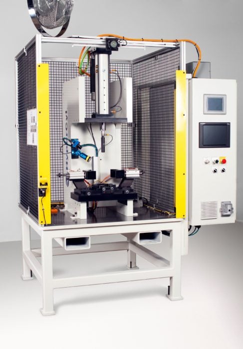
    To differentiate between linear or rotary actuators, consider their motion profile. In the case of linear actuators, they generate push or pull movement along a straight line through rotary motion. Different types of linear actuators utilize energy sources such as electricity, pressurized hydraulic fluid, and compressed air or gas to power the motor that creates that rotary motion.

    Operators have control over the speed of actuator movement, ensuring safe and efficient processing with high repeatability and positioning precision. Industries from aerospace and defense to agriculture and food and beverage make use of linear actuators for their cost-effectiveness and versatility in wide-ranging automation applications.

    Different Types of Linear Actuators

    To best suit the needs of these varied industries, engineers have developed three main types of actuators: mechanical/electromechanical, hydraulic, and pneumatic.

    Mechanical and Electromechanical Linear Actuators

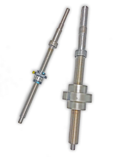
    An external force activates a mechanical linear actuator, and an internal force for electromechanical linear actuators, but both derive linear motion by converting rotary motion. A motor such as a servo, a stepper, or a gearmotor utilizing AC or DC power typically fuels electromechanical linear actuators. Among electromechanical actuators, you’ll frequently find ball-screw, roller-screw (also known as planetary screws), or lead-screw designs. All three contain a rotating nut that moves linearly along a screw shaft. Using these actuators can provide more control over distance and force, though they are typically more expensive than other types.

    Hydraulic Linear Actuators

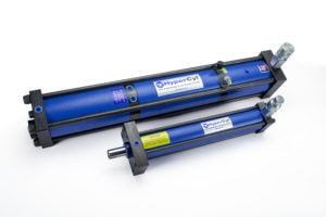
    Rather than an electric signal or manual motion, hydraulic linear actuators gain power from oil or other pressurized hydraulic fluid. You’ll find these in operation in machines and equipment situated in rugged environments and terrain, such as construction sites or mining excavations. Hydraulic linear actuators are ideal for high-force and high-power applications, especially where you require shock load capacity and consistent pressure. However, these actuators need a lot of power, often suffer from leakages, and are quite noisy. You can also damage hydraulic actuators if you operate them at high temperatures, and they require added parts for full functionality.

    Pneumatic Linear Actuators

    Pneumatic linear actuators convert compressed air or gas energy to produce straight motion. Speed and cost are the primary benefits of these actuators. They’re reliable and effective for applications that require the rate of linear motion in objects to be up to 60 inches per second. However, you’ll also need a compressor, which generates noise during operation, and pressure losses disqualify these actuators from applications needing absolute movement precision.

    Features of Linear Actuators

    Linear actuators have enjoyed widespread usage because of their reliability and versatility. Actuators pair with various power sources and come in numerous design configurations, such as screw, rod, or belt type, that provide the requisite force, precision, and acceleration/deceleration speed for multiple applications.

    Requiring very little operator maintenance, actuators can have a long working life. You can deploy them in harsh environments, and they still provide high repetition, accurate positioning, and precision movements. Depending on the type you use, linear actuators can also be quite compact.

    Industries and Applications for Linear Actuators

    You will find linear actuators in many industries. Some of the most common are:

    •     Aerospace
    •     Agriculture
    •     Automotive
    •     Clean and renewable energy
    •     Food and beverage
    •     HVAC
    •     Marine
    •     Military
    •     Packaging
    •     Pharmaceutical
    •     Robotics

    Actuators are critical components in many processes within these industries. For example, actuators capture and harness solar, tidal, and wind energy to power equipment and buildings. You can find them in automotive features ranging from power liftgates to sunroofs. Tanks use actuators to elevate their weapons systems. Also, factories in numerous industrial sectors use actuators to operate conveyor belts, robots, and other automated equipment.

    High-Quality Linear Actuators From HyperCyl

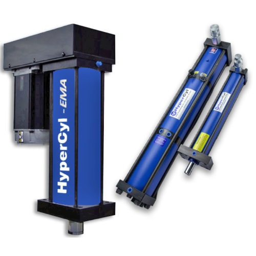
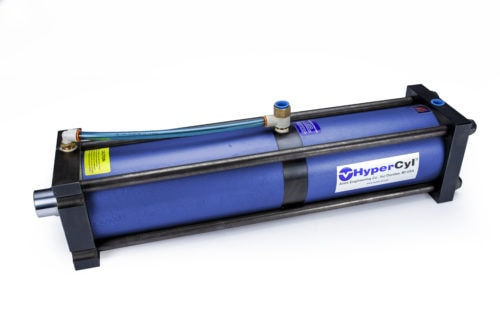
    For reliable, precision linear servo actuators for industrial processes or finished goods, Aries Engineering Company, Inc. and HyperCyl systems have what you need. Serving a diverse customer base in industries such as automotive, medical, and aerospace, AEC/HyperCyl provides both Ball Screw and Roller Screw actuators with superior performance in real-world assembly and forming applications, as well as our Application Test Lab for potential assembly evaluation.

    Leveraging our expert engineers, product knowledge, and customer feedback, we ensure that HyperCyl fabricates electromechanical, hydraulic, and pneumatic linear actuator systems to meet the highest quality standards. To find out more about our actuator solutions, contact us or request a quote today.

  2. Ball Screw Actuators vs. Roller Screw Actuators

    Comments Off on Ball Screw Actuators vs. Roller Screw Actuators

    Actuators are mechanical devices that convert energy into motion. These components are incorporated into a wide variety of products, from industrial equipment to household electronics. The energy source of an actuator can be electric, hydraulic, or pneumatic power.

    High-quality, heavy-duty actuators are critical for industrial operations, where they are responsible for facilitating linear and rotary motion to convey materials and operate equipment. For heavy-duty operations, ball screw actuators and roller screw actuators are ideal. We will explain the characteristics, benefits, and differences between ball screw and roller screw actuators so you can choose the one that best suits your needs.

    Ball Screw Actuators

    Ball screw actuators convert rotary motion to linear motion. They feature a nut mounted on a grooved screw shaft. Inside the nut, recirculating balls roll within the groves of the screw shaft. As the screw turns, the nut moves up and down the shaft along the grooves, creating linear motion that can be finely controlled by turning the screw. Ball screw actuators provide precise control for medium-duty to heavy load-bearing applications and can accommodate high-speed processes.

    Ball Screw Applications

    Ball screw actuators provide smooth, energy-efficient motion with exceptional accuracy and precision control. They offer continuous high-speed, high-force movement for long periods of time. These benefits make ball screws ideal for:

    • Sawmills
    • Wind turbines
    • Solar panels
    • Vehicle power steering
    • Assembly equipment

    Roller Screw Actuators

    Roller screws have a similar construction to ball screws, but instead of recirculating balls, they contain rollers that are threaded to match the threads on the main screw shaft. Since the rollers do not touch each other, they do not interfere with each other’s motion and can operate significantly faster than ball screws. The individual rollers have greater surface area contact with the main shaft than recirculating balls, so they have higher axial load characteristics, higher dynamic load capabilities and thus longer life than comparable ball screws. They also generate more heat and require more lubrication at tighter intervals.

    Roller Screw Applications

    Roller screws can withstand high force and repetitive motions for long periods of time. They can be controlled with a high degree of precision, and their extensive surface area provides additional stress dispersion in high-force applications, such as:

    • Automotive and aerospace manufacturing
    • Metal casting and molding
    • Paint spraying
    • Pressing, inserting, and riveting
    • Precision CNC machining
    • Automated, high-speed manufacturing equipment

    Which Actuator Is Right for You?

    Ball and roller screws each offer unique advantages for different applications. To determine which actuator is ideal for your needs, consider the following:

    • Operational Life: In general, roller screws have a longer service life and offer good ROI when operated for extended periods of time. For projects lasting less than three years, ball screws are highly effective and make an excellent investment. Depending on the budget and length of your project, ball screws may be ideal for short-term, low-budget projects, while roller screws would be better for long-term applications.
    • Expected Force: Longevity is greatly affected by the amount of force exerted. Roller screws are better than ball screws for heavy loads over eight tons. For applications with lower load capacity, balls screws represent an excellent low-cost option.
    • Maintenance Frequency: Due to the amount of friction and heat they generate, roller screws often require more lubricant and maintenance than ball screws, especially in high-speed operations. Both types of actuators operate best with sufficient lubrication and regular preventative maintenance.
    • Contact Area: Due to the lack of contact between rollers and the bearing, roller screws transmit more force more quickly. Ball screws must make contact between balls and the bearing, so this can interfere with ball motion, reducing efficiency and increasing wear on the actuator elements.
    • Cost: Ball screw actuators are significantly less expensive to obtain, maintain, and repair. Components are readily available open-market, and their simple design makes them easy to fix. Roller screws, on the other hand, are more complex and contain more specialized components, which makes parts harder to source and more expensive to repair or replace.

    Request a Quote on Quality Actuators from HyperCyl

    HyperCyl is a leading developer and manufacturer of cutting-edge assembly and forming technology. We offer a selection of ball screw, roller screw, and other actuator designs to meet the needs of demanding applications in the commercial, manufacturing, defense, and automation industries. To learn more about our innovative motion solutions, contact us today or request a quote!

  3. Hydraulic vs. Pneumatic vs. Electric Actuators

    Comments Off on Hydraulic vs. Pneumatic vs. Electric Actuators


    Actuators are mechanical devices that use energy to generate motion. Manual or automatic control commands initiate change in physical systems, creating motion to perform a task. Actuators allow machines to lift, block, clamp, eject and more.

    Depending on the type of energy source used to produce motion, three main types of actuators are available: hydraulic, pneumatic and electric. Below we’ll review the characteristics of these actuators as well as their applications and advantages.

    Hydraulic Actuators

    Known as the most commonly used energy conversion system, hydraulic actuators are an especially popular choice for systems requiring high-force automation equipment. These actuators rely on oil fluid compression.

    A variety of heavy-duty applications use hydraulic actuators to produce anywhere from ½ to 4,000 tons of force. These potential applications include:

    • Cargo handling
    • Large construction equipment
    • Military weapons
    • Marine propulsion
    • Transportation systems

    Advantages of Hydraulic Actuators

    Hydraulic actuators bring the following benefits to an operation:

    • Good strength-to-weight ratio: Hydraulic actuators can deliver tremendous force relative to their weight.
    • Safety: They include various safety features, including rod locks, dump valves that quickly dissipate energy, and bypass valves that close off high-pressure oil when generating motion.
    • Mobility: Hydraulic actuators are also compact enough to take on mobile operations, servicing trucks and other heavy transportation equipment.

    Pneumatic Actuators

    Most pneumatic actuators feature compression rates of 80 to 100 psi, making them a more stable and safe option for applications requiring less force. These actuators capture atmospheric air and compress it at higher pressures to generate motion. The specific parts of a pneumatic actuator include the actuator, storage tank, system of delivery hoses, motor and compressor unit.

    Advantages of Pneumatic Actuators

    The benefits of pneumatic actuators include:

    • Speed: The fastest actuators are pneumatic. Fast cycle rates contribute to greater productivity and profit.
    • Cost effectiveness: Pneumatic actuators have lower upfront costs compared to other actuators. They return their initial investment quickly, especially for moderate-duty applications.
    • Simplicity: Pneumatic actuators are relatively simple, so they are less likely to malfunction and easier to repair if they do.

    Electric Actuators

    Electric actuators use a motor to convert electric energy into torque, producing motion. They use a variety of mechanical components—gears, planetary roller screws, ball screws, lead screws—to generate linear energy from rotational energy.

    Small electric actuators are best for low- to medium-duty applications, such as packaging, factory robotics, automotive manufacturing and medical devices. Large electric actuators can produce up to 50,000 lbs of force.

    Advantages of Electric Actuators

    Electric actuators provide the following main benefits:

    • Speed: Electric actuators respond quickly to generate motion, with speeds of up to 20 in./sec.
    • Precision: Unlike hydraulic and pneumatic actuators, electric actuators are highly precise because they are not subject to inherent tolerances.
    • Cleanliness: Electric actuators use electricity, a clean energy source, eliminating the risk of leaks.

    Electric Actuators from Aries Engineering

    Aries Engineering produces the HyperCyl-EMA, one of the most reliable electromechanical actuators on the market. This servo-driven actuator works well for precision assembly applications and as substitutes for hydraulic or pneumatic actuators. Our electric actuators are capable of 0.0025 mm, ram speeds of up to 500 mm/sec, and up to 50,000 lbs of output. The HyperCyl-EMA has served customers in the aerospace, automotive, defense, medical, appliance, electronics and transportation industries.

    Find the Actuator You Need at Aries Engineering

    Aries Engineering Co., Inc. manufactures a line of “hydra-pneumatic” presses and cylinders for many types of assembly applications. We pioneered oil/air compression in 1994 and continue to serve clients across the manufacturing, industrial automation, defense and commercial industries.

    If you would like to find out more about our HyperCyl-EMA electric actuators and other products, contact us today. To get started on your next solution, request a quote at any time.

  4. What Is a Servo Actuator?

    Comments Off on What Is a Servo Actuator?

    Actuators are designed to convert energy from different sources, such as electric currents, pneumatic pressure, or hydraulic fluid pressure, into motion. There are three main types of actuators: pneumatic actuators, hydraulic actuators, and servo actuators.

    Servo actuators use feedback signals to move or control mechanical systems in a highly efficient and safe manner. This is possible because servo actuators have a controller that can accurately compare, contrast, and calculate the potential differences between the desired results and system conditions on a real-time basis before the motion starts.

    Servo actuators use a servo motor in either an open or closed-loop control system. Several servo actuator models have a food-grade approved coating of paint for more sanitary wash-down applications.

    Servo actuators are available in both ball and roller screw configurations, like the HyperCyl-EMA, which has several options available for output force. They have an extended service life because they can easily be re-lubricated without disassembly.

    How Does a Servo Actuator Work?

    A servo system has three main core components:

    • A controlled device that allows the actuator to successfully operate
    • An output sensor/signal that acts as the main controller to tell the device what to do
    • A position sensor, encoder feedback, or load cell to provide accurate system feedback readings

    Servo Actuator Control Systems

    The control systems, which allow the actuators to operate, come in two different designs.

    Closed-Loop Control System

    Commonly referred to as feedback controllers, this type of control system is fully automatic and uses the input of the system and the output of the system controls to function. Closed-loop control systems are usually very accurate.

    Open-Loop Control System

    Commonly referred to as a non-feedback system, this type of control system is not automatic and doesn’t have a feedback loop. The output of the system depends on the input. However, the input or controller is independent of the output produced by the system. Open-loop systems do not measure the device’s output or use the information as input for further consideration.

    How Do Servo Actuator Controls Work?

    Servo actuators are controlled by a feedback signal generated by comparing the output signal and the reference-input signal rather than a variable-input signal. Whenever a command or reference-input signal is applied to the system, it is immediately compared with the system’s output-reference signal produced by the output sensor. Lastly, a third signal is produced by the servo actuator’s feedback system before it starts to move.

    The device can also be programmed with certain instructions and autonomously perform the movements on its own. For example, the actuator can receive a command to go to a specific position and immediately follow the command. This makes them very different from comparable pneumatic valves (pneumatic actuators) and pumps (hydraulic actuators), which can only follow simple instructions to ‘power on’ or ‘power off’ on their own.

    Applications of Servo Actuators

    There are numerous applications of servo actuators. Some of these include toys, home electronics, computers, drones, and remote controlled cars.

    Servo actuators also often play a crucial role in the function of both land- and sea-based vehicles – such as automobiles, airplanes, helicopters, and submarines.

    Automobiles

    Servo actuators can contribute to the function of these parts in automobiles:

    • Engine Cradle Assembly
    • Engine Sub-Assembly
    • Ball Joints and Bushings

    Airplanes and Helicopters

    Servo actuators adjust the wing angle of airplanes and control steering by moving the levers back and forth. Airplanes can easily “fly-by-wire” when they have a servo-controlled main system instead of an older hydraulic-powered one.

    Servo actuators can also control the speed of a helicopter by moving a swash plate, which can tilt the pitch of the blades in a certain direction to give it more lift.

    Submarines

    Servo actuators can adjust the submarine’s steering, bay doors, hatches, and rudder.

    Servo Actuators at HyperCyl

    HyperCyl has been providing servo actuators and other high quality assembly and forming solutions for customers in the industrial automation, commercial, manufacturing, and defense industries for over 25 years. Please contact us or request a quote today to learn more about servo actuators or our other product and service offerings. Our highly experienced team members would be happy to use their expertise to talk with you and help you identify the appropriate actuator for your organization’s specific needs.

  5. Why Use Air Over Oil Cylinders?

    Comments Off on Why Use Air Over Oil Cylinders?

    HPS (Tandem, minimal profile) Air over oil cylinders are pneumatic cylinders designed to produce greater force than standard pneumatic cylinders of the same bore size. They incorporate both oil and air within the mechanism, creating a hybrid pneumatic-hydraulic cylinder that intensifies the amount of force generated by compressed air input.

    HyperCyl takes the innovative design of hybrid air over oil cylinders to the next level with our patented rod and piston mechanism. Unlike other designs, our cylinders do not use an external oil reservoir. Instead, the oil reservoir is completely sealed and incorporated into the cylinder itself. Our air over oil cylinders uses compressed air on the piston to exert force within a sealed hydraulic chamber by pneumatically driving a rod into the oil reservoir, which is situated behind the work piston.

    Why Use Air Over Oil Cylinders?

    Air over oil cylinders offer a host of unique advantages over more traditional pneumatic systems. Since compressed air is ubiquitous in virtually every industrial setting, it offers a convenient source of clean power that can easily be intensified using HyperCyl’s air over oil cylinders.

    Our state-of-the-art air over oil cylinder design offers a low-cost, highly efficient means of converting compressed air to smooth fluid force. HyperCyl’s air over oil cylinders only use 25% – 30% of compressed air when compared with multi-piston pneumatic cylinders for the same operation.

    While many companies are phasing out hydraulic power units and cylinders, the HyperCyl air over oil cylinders offer a cost-effective solution for facilities that want the power of a hydraulic system in a smaller package. Our air over oil intensifier units can provide up to 200 tons of force while using significantly less space than traditional hydraulic systems. The smaller size of our air over oil cylinders allows for reduced bore size compared to standard multi-stage pneumatic cylinders.

    Our air over oil cylinders make no more sound than a standard pneumatic cylinder. Since there is no power unit like hydraulics, you enjoy less noise, less heat generation, and no continuously running motor. Energy is needed only while HyperCyl is moving; at rest zero noise and zero energy is realized. To suit your specific needs, we offer six models of air over oil intensifier cylinders suitable for a broad variety of industries and applications. In addition, we are pleased to work with you to create custom stroke cylinders quickly and efficiently, within your budget.

    Partnering With HyperCyl for Air Over Oil Cylinders

    For more than 25 years, HyperCyl has been a leading expert in the design and manufacture of air over oil, or hydra-pneumatic, cylinders. Our extensive expertise extends to servo-controlled actuators, assembly cells, and presses using our cutting-edge cylinder technology. As a privately-owned company based out of Dundee, Michigan, we are proud to produce our products in America.

    We are dedicated to helping our customers find the perfect motion solutions for their particular needs. Our seasoned experts will work closely with you to determine the appropriate force and stroke requirements for optimal power and efficiency. Each of our air-over-oil cylinders offers unique features to enhance your operations, soft initial part contact and enhanced energy efficiency. The pressure stroke of the cylinder can be regulated separately from the approach stroke, allowing you to fully tailor your force and energy usage for optimal cost savings.

    At HyperCyl, we offer a variety of triggering mechanisms for high-pressure actuation, without the need for cylinder alterations. This mechanism can be triggered based on a pressure threshold (ELT sensor), specified stroke distance (LVDT), or a simple proximity sensor. Other standard features of our air over oil cylinders include:

    • Complete air/oil separation
    • Wear bands on internal pistons for increased life
    • Variable operating positions or attitudes
    • No external oil reservoir
    • Up to 200 tons linear output force
    • Three primary moving components
    • NFPA medium-duty mounting
    • Tie rods with 100,000 psi tensile-strength
    • Operation and maintenance manual
    • Heavy-duty construction for long service life
    • 4.5 million MTBF (mean time before failure)
    • 20 million cycle service life
    • Accessories include gauge kits, sensors, total stroke limiters, alignment couplers, rod locks, and more
    • HyperCyl’s “IntelliCyl” package offers in-process validation of each part thereby dramatically reducing part-nonconformance, scrap rates, and check QTY of fixtures involved
    • Limited Lifetime warranty for cylinder materials and workmanship

    Superior Quality and Exceptional Workmanship by HyperCyl

    Since 1994, HyperCyl has been providing innovative solutions to some of the most challenging motion problems. Our years of experience and commitment to quality have made us a leading provider of actuators and press systems for customers in almost any industry. We hold our products to the highest standard, consistent with the Buy American Act and Made in the USA requirements.

    To learn more about our extensive selection of air over oil cylinders and other actuation solutions, contact us today or request a quote.

  6. A Guide to Pneumatic Cylinder Installation

    Comments Off on A Guide to Pneumatic Cylinder Installation

    Pneumatic cylinders are mechanical components that provide linear force to various devices and systems. They generate the force by applying compressed air to one side of a sealed barrel and exhausting it from the other side. This action causes the piston/rod assembly contained inside to extend or retract.

    It is important to install pneumatic cylinders correctly. Otherwise, there is a risk of inaccurate or unreliable operation and premature failure. This is especially true for hydra-pneumatic cylinders, which generate high forces in a small package. As such, incorrect installation can lead to severe equipment damage and/or operator injury.

    Below, we discuss how to install a pneumatic cylinder properly. Additionally, we highlight the importance of testing the system before putting it into operation and the precautions to take when performing installations.

    How Do I Install a Pneumatic Cylinder Properly?

    Pneumatic CylinderThere are two essential fixing points to consider when installing a pneumatic cylinder: the body and the piston rod end. How these points are fixed depends on the application.

    In static applications, the cylinder can be mounted to the machine bench and fixed rigidly to its structure. Both pneumatic and hydra-pneumatic cylinders are typically mounted with a rectangular front flange mount (also sometimes called an MF1 mount or FH mount) or tapped holes in the front of the face (also sometimes called an MR1 mount or UH mount) due to the high forces generated. However, some pneumatic cylinders use a semi-rigid trunnion mounting method (MT1) that utilizes body supports or pivots and clevis pins. It allows them to rotate as they follow the extension and retraction of the piston rod. In rare cases, a side lug mounting method (MS2T mount) may be used.

    In complex linkage applications, the cylinder must be able to swivel on its mountings. There are several solutions to this mounting requirement. For example, a front clevis, central trunnion, or rear hinge can be used on the body of the cylinder to allow the cylinder and load system to achieve different degrees of balance. Alternatively, a clevis, front hinge, or universal eye can be used at the end of the piston rod to mount swivel attachments. If a trunnion mounting method is chosen, it is essential to ensure the cylinder can oscillate freely on the mountings and the pipe connections can flex when in use.

    Some of the things to keep in mind when installing a pneumatic cylinder include:

    • Minimize or eliminate side loading. Side loading is highly damaging to pneumatic cylinders. Ensuring the cylinder is correctly aligned and properly mounted can reduce the risk of it occurring. An alignment coupler or die set coupling can also eliminate or minimize side loading when attaching the rod end to the tooling.
    • Lubricate the bearing slides and trunnions. The bearing slides and trunnions should be lubricated as per the manufacturer’s guidelines.

    Why Should I Test the System?

    Before putting a cylinder into operation, it is critical to test the entire system to ensure the component actuates with minimal resistance and the rod experiences minimal side loading. Testing operations can be conducted by using a flexible air line and blow gun to check the cylinder is installed properly and able to move freely at the published minimum operating pressures. For hydra-pneumatic cylinders, it is vital to test them in low pressures (approach and retract) without going into high pressures (intensification) to ensure the tooling and overall setup are aligned correctly. These testing operations should follow the manufacturer’s guidelines for sequencing the cylinder for approach, retract, and intensification.

    What Precautions Should I Take When Installing Pneumatic Cylinders?

    There are many considerations to keep in mind when installing a pneumatic cylinder. Be sure to take the following precautions to ensure safe installation:

    • Avoid attaching unsupported loads directly to the piston rod. Use roller guides or a slide to support the load.
    • Minimize bending moments. Suspend the rod end from a roller track or another form of external guidance if it has a long out-stroke and high shear weight.  Install external bearings, or guides, to reduce side loading wherever possible.
    • Align the pneumatic cylinder and guided loads properly. The use of alignment couplers, or die set couplers, will overcome minimal alignment issues.
    • Use properly conditioned air, according to the manufacturer’s recommendations.  Particulate filtration, removal of water (moisture), and other contaminants is important for nearly every manufacturer’s cylinders and pneumatic valves.

    Hydra-Pneumatic Cylinder Solutions at HyperCyl

    If you’re looking for hydra-pneumatic cylinders and presses for your assembly and forming operations, turn to the experts at HyperCyl. Equipped with more than 20 years of experience, we have the knowledge and skills to help you identify the right equipment for your needs. Our products are carefully designed, assembled, and installed to allow for greater process control, higher retract force, and better cost savings.

    For more information about pneumatic cylinders or our product and service offerings, contact us or request a quote today.

  7. The Different Types of Industrial Press Systems

    Comments Off on The Different Types of Industrial Press Systems

    An industrial press — more commonly called a machine press — can perform a broad range of tasks that require the application of pressure to form and shape metal. In addition to forming, industrial presses can accommodate tooling for cutting, assembly, and more. Presses are available in many different sizes and may use various energy sources.

    There are three types of standard press system frames:

    • The H-frame press allows for easy material pass-through; front to back &/or left to right.
    • The C-frame press facilitates easy loading/unloading from the front, or from either side.
    • The CGB-frame press features a low-profile design and accommodates bench-top use.

    The ideal frame and method of applying force will depend on the application. There are five types of industrial presses commonly used in machine shops.

    Manual Press

    (Click to Expand)

    The Different Types of Industrial Press Systems

    Manual presses are sometimes known as a workshop press or arbor press. A manual press derives its power from a human operator. The manual press’s ram can be moved in a linear motion and generates forces using simple methods like leverage. Affordable and straightforward in design, manual presses are ideal for bench-mounting and performing light-duty tasks, like bending and piercing for very low volume operations. The operator controls the press by moving the ram and applying force using a lever or handle.

    Pneumatic Press

    A pneumatic press uses compressed air to increase the cylinder’s internal pressure, generating linear motion and force. Pneumatic presses generate a relatively low maximum force dependent on the pressure of the regulated air source and the size of the cylinder bore. Although the maximum force may be low, pneumatic presses minimize operator fatigue with no tactile feedback.

    Pneumatic presses are typically cost-effective for minimal to periodic use, providing quick and consistent force throughout the stroke range. Typical processes for pneumatic presses may include punching, bending, extruding, forming, and shearing.

    Pneumatic Intensified (Air/Oil) Press

    These presses are also called hydra-pneumatic presses, or air over oil presses. They use an air over oil intensifier cylinder for the press’s motion. They are controlled pneumatically, but they have a trapped section of hydraulic oil in the cylinder which gets intensified to provide higher forces (up to 200 tons). Air/Oil presses provide a smooth controlled power stroke to the workpiece. A pressure regulator controls the power stroke force, and a hard stop in the cylinder, part, or tooling controls the power stroke length. Hydra-pneumatic presses typically use significantly less compressed air than standard pneumatic presses, so they are more efficient for production environments.

    Hydraulic Assembly Press

    Pneumo-Hydraulic CylinderA hydraulic assembly press uses a hydraulic cylinder filled with oil, and a hydraulic power unit powered by an electric motor to move the ram and generate force through the hydraulic cylinder. Hydraulic presses are available in a broad range of sizes and capabilities. In general, the hydraulic cylinders’ bore size and regulated operating pressure determine the machine’s maximum force. The hydraulic press delivers consistent force throughout the stroke range and is adjustable based on a pressure switch or force setting.

    Servo-Electric Press

    A servo-electric press delivers fuller control with flexibility and consistent force throughout the stroke. The servo-electric press is gaining popularity in recent years as the prices become lower. This industrial press type has several advantages, including a long lifespan, energy efficiency, and simple maintenance without messy oil and power units. It uses plant electricity to generate linear motion through a servo motor or drive unit integrated with a ball screw or roller screw actuator. Servo-electric presses also feature high precision and deliver full tonnage throughout the stroke without producing substantial noise, and have complete controllability at the touch of a button.

    Rely on HyperCyl for Your Industrial Press Systems

    An industrial press delivers force for cutting, assembling, and forming workpieces. With various industrial press systems to choose from, there is sure to be a press that suits your application. At HyperCyl, we have been delivering high-quality hydra-pneumatic press solutions since our establishment in 1994, and HyperCyl-EMA servo press solutions since 2010. Aries Engineering/HyperCyl is a privately-owned, American company with headquarters in Dundee, Michigan.

    HyperCyl has been a member of the NFPA since the year 2000, and a charter member of the Assembly Show. We offer UL, CSA, CE panel certifications for any given system. We also hold seven trademarks and six patents on our cutting edge technology.

    To learn more about our services and capabilities, reach out to us, or request a quote.


  8. Everything You Need to Know About Hydra-Pneumatic Cylinders

    Comments Off on Everything You Need to Know About Hydra-Pneumatic Cylinders

    Hydra-pneumatic cylinders—commonly referred to in the industry as hydro-pneumatic cylinders, air-over-oil cylinders, or intensifier cylinders—are pneumatically controlled cylinders engineered to generate higher hydraulic pressures to achieve a greater stroke force than can be attained by solely pneumatic cylinders of the same bore size. For example, a 5-inch bore pneumatic cylinder can output less than 1 ton of force at 100 psi, while a 5-inch bore hydra-pneumatic cylinder can produce up to 10, 15, or 20 tons of force, depending on the design.

    The following blog post provides an overview of hydra-pneumatic cylinders, including how they work, key features, typical applications, and solutions at HyperCyl.

    How Do Hydra-Pneumatic Cylinders Work?

    Pneumo-Hydraulic CylinderIn contrast to strictly pneumatic or strictly hydraulic cylinders, these hybrid cylinders rely on the surface area differential of an internal pneumatic piston-rod assembly to significantly increase the pressure of trapped oil above the work piston, to provide an intensified hydraulic cylinder output force. Initially, they function similarly to pneumatic, double-acting cylinders, extending and retracting to the workpiece with output forces typical of pneumatic cylinders. However, once in contact with the workpiece, a second pneumatically controlled cylinder section drives a rod into the oil section, sealing it off, and intensifying the internal pressure. The intensified oil pressure pushes against the work piston, producing an increased output thrust, typical of hydraulic cylinders.

    Similar to other double-acting pneumatic cylinders, hydra-pneumatic cylinders utilize valves to control their motion. They have one four-way valve to control approach and retract motion, and one four-way valve to control oil pressure intensification. This design combines the advantages of pneumatic and hydraulic cylinders without any of the disadvantages (e.g., excess heat and noise, space limits, or risk of leaks). Compared to strictly pneumatic cylinders with a multi-stage design, these cylinders consume only about 1/4 to 1/3 of the air.

    Key Features of Hydra-Pneumatic Cylinders

    While hydra-pneumatic cylinders come in a variety of designs to suit different applications, some of their key features include:

    • HPX Hydra-pneumatic cylinder
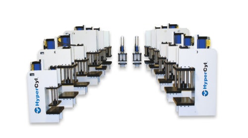
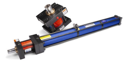
Three major moving components
    • Simple control circuits
    • Total/air oil separation on both sides of the oil
    • Wear bands on the reservoir and work pistons
    • Linear output forces up to 200 tons
    • Heavy-duty construction for durability and reliability
    • Tie rods with tensile strengths of 100,000 psi
    • Mean time between failure (MTBF) of 4.7 million strokes
    • Service life of 20 million strokes
    • Operational capacities in any position or attitude
    • Medium-duty mounting styles compliant with National Fluid Power Association (NFPA)
    • Included repair manual and field serviceable seal kits
    • Options for gage kits, sensors, total stroke limiters, alignment couplers, and more

    Typical Industry Applications for Hydra-Pneumatic Cylinders

    InetlliCyl Pneumo-Hydraulic Cylinder
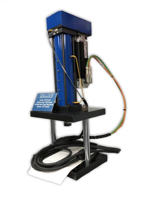
The full line (six series) of HyperCyl® hydra-pneumatic cylinders are designed for machine builders and OEMs to use in their own presses and automation, as well as for use in HyperCyl supplied presses. HyperCyl presses are available with “C” frames or “H” frames, unguided, two-column guided, or four-column guided upper bolsters, and bench-mounted, pedestal, or machine base configurations. Due to their modular design, machine designers can choose a simple frame and drive unit design that facilitates integration into a larger assembly process, or a turnkey design that incorporates automation technology, controls, and more.

    HyperCyl presses find use in a wide range of production applications, such as:

    • Part insertion and assembly
    • Material piercing
    • Clinching
    • Staking
    • Drawing
    • Marking
    • Cutting
    • Pressing
    • Folding
    • Riveting

    Why Partner With HyperCyl for Your Hydra-Pneumatic Cylinder Needs?

    HyperCyl by Aries Engineering Company (AEC) is a privately owned company based in Dundee, Michigan. We specialize in the manufacture of hydra-pneumatic cylinders and presses for assembly, piercing, and forming applications. By utilizing our cylinders, our customers benefit from the following:

    • Greater Process Control: Our cylinders allow for separate regulation of the approach stroke and power stroke, which allows for more complete control over the process without the need for cylinder reconfiguration.
    • Higher Retract Force: Since our cylinders generate greater retract forces, they can accommodate the attachment of heavier tooling.
    • No Stored Energy: Our cylinders do not use mechanical springs to move the pistons, which can break and hinder/halt operations. There are no unexpected motions from stored energy in HyperCyl cylinders.
    • Better Cost Savings: Our cylinders consume less air than other pneumatic cylinders. Our cylinders take up less space, generate less heat and noise, and cost less to purchase than a hydraulic cylinder and power unit. Additionally, they offer faster operational speeds and a smaller risk of leakage.

    All of these qualities translate to lower investment, operational, and/or maintenance costs.

    Source Hydra-Pneumatic Cylinders from HyperCyl

    Since 1994, we’ve helped our customers determine the force and stroke requirements for their applications to help them design and purchase the right equipment for their needs. By evaluating their parts with our in-house equipment, we help identify the forces needed, and which actuator is best suited for their assembly, piercing, or forming application. All supplied materials are accompanied by complete evaluation documentation and reporting. We also offer access to an extensive database of hundreds of previous assembly and forming applications for examples of our capabilities.

    To learn more about our product solutions and how they can benefit your assembly or forming application, contact us today. To discuss your application requirements with one of our experts, request a quote.